LJ Relays Featured Project
EM Relay Technology’s Part in Modern T&D Protection
Safe and reliable electric power at a reasonable cost is the goal of any electric utility. How this goal is achieved has improved over the years. Many of the improvements were driven by enhancements in the world of protective relaying systems, as the electric utility industry went from using Electromechanical Relays (EM) to Solid State Relays (SSR) and then to Microprocessor based Relays (μP). And as the technology evolved, the industry has benefited – as witnessed by constant improvements in two common metrics – the System Average Interruption Duration Index [SAIDI] and the System Average Interruption Frequency Index [SAIFI].
However, during this technical and performance evolution, companies like Relay & Power Systems (who makes a specialized EM relay called the LJ Relay that is used in many thousands of power systems throughout North America) have seen continued and increasing demand for the older EM technology.
How can this be? Why is there continuing interest in mature EM technology such as the LJ relay?
RPS has recently interviewed several utility users and learned that EM relays like the LJ provide a prudent alternative for a wide variety of power system configurations challenges. One user in particular, a major northeast electrical utility, was instrumental in working with RPS (then known as Relay Associates) in the development and evolution of the LJ relay several decades ago. This utility user shared a few applications for which they use the relay today.
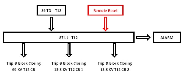
Substations that are equipped with two, three, or more large power transformers, near simultaneous actuation of all lockout relays is beyond design basis and may result in a significant number of customer interruptions. When faced with this situation, some utilities have chosen to install LJ relays rather than traditional lockout relays for transformer and bus differential relaying schemes. This application allows operators to quickly restore service to customers using supervisory control in the unlikely event that multiple components trip out almost simultaneously (See Figure 1).

Figure 1 – Substation One Line Diagram

Illustration of Transformer T12 LJ Application
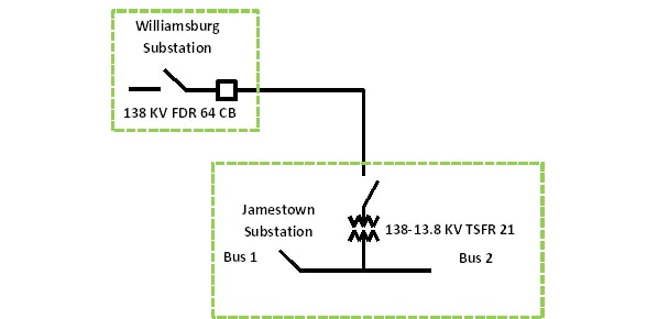
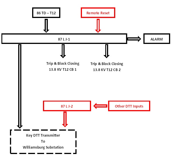
When transformers are tapped directly off transmission lines, Direct Transfer Tripping (DTT) is installed to trip remote circuit breakers. In addition to the simultaneous trip concern that could trip remote circuit breakers as well as local circuit breakers, a second concern is that transients at the local substation could cause a direct transfer trip signal to be sent to the remote substation. In this case, LJ relays, which have high energy input requirements, are installed between the initiating device and the DTT transmitter (See Figure 2)

Figure 2 – Substation One Line Diagram
This is illustrated in Figure 2 for Jamestown and Williamsburg Substations as Jamestown Substation is not equipped with 138 KV fault interrupting devices.
In some high transient environments/conditions the rapid response and low energy requirements of μP relays has resulted in unwanted DTT (Direct Transfer Trip) actuations when trip signals are wired directly to μP relays. One solution is to place high speed LJ relays near μP relays and to use the high speed (4ms), transient resistant nature of EM relays like the LJ to serve as a buffer between wired inputs and μP relays.
As power systems continue to evolve and customer expectations for high quality, dependable power continues to increase, proven EM relay technology like the LJ are providing a prudent alternative that can do their small part to help utilities cost effectively and reliably achieve their SAIDI and SAIFI goals.

Illustration of Transformer T21 LJ Application
