LJ Relays Application Guide
Modern Electromechanical Relay Applications
Problem – Electric utilities use shielded control cables to minimize transients in control circuits and μP relays are designed and tested to withstand transient voltages. However, an additional consideration is that the rapid response and low energy requirements of μP relays has resulted in unwanted DTT (Direct Transfer Trip) actuations when trip signals are wired directly to μP relays. In fact, utilities purchasing LJ relays have reported that transients in control scheme wiring have actually resulted in unwanted DTT actuations.
Solution – Place high speed LJ relays near μP relays and to use high speed LJ relays to serve as a buffer between wired inputs and μP relays.
This is illustrated in Figures 2 & 3 for Conshohocken and Wyomissing Substations. In this application, Wyomissing Substation is not equipped with 138 KV fault interrupting devices and DTT is needed to trip the 138 KV circuit breaker at Conshohocken in the event that a transformer failure occurs at Wyomissing.

Figure 3 – LJ Interposing Relay Application with μP DTT Transmitters
Problem – Substations that are equipped with two, three, or more large power transformers, simultaneous actuation of multiple lockout relays is beyond design basis and can result in a significant number of customer interruptions.
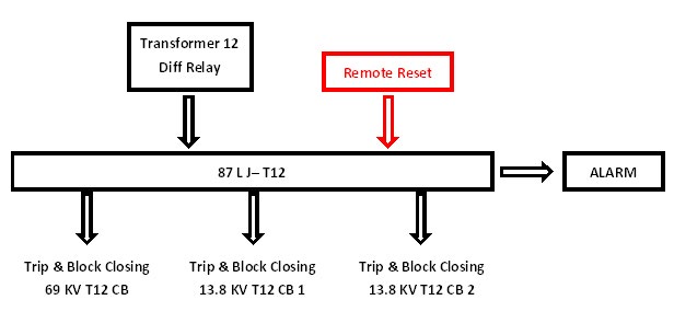
Solution – When faced with this possibility, some utilities have chosen to install LJ relays with remote reset capability rather than traditional, hand reset, lockout relays for transformer and bus differential relaying schemes. This application allows operators to quickly restore service to customers, using supervisory control, if multiple components trip out simultaneously.
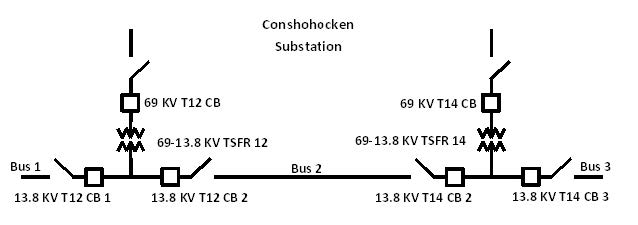
This is illustrated in Figures 4 and 5 for Conshohocken Substation where LJ relays are actuated by Transformer T12, Transformer T14, Bus 1, Bus 2, and Bus 3 differential relays to trip circuit breakers when a fault occurs.

Figure 4 – Conshohocken Substation Configuration
This remote reset feature allows operators to restore a transformer or bus to service when substation video images do not show signs of arcing and damaged insulators, sudden pressure relays have not actuated, and other indicators of component failure are not evident at the remote power control center.

Figure 5 – Illustration of LJ application for Transformer T12 Differential Protection
Problem – Substations that are equipped with protective relays that have limited trip output contacts, such as electromechanical bus differential relays.
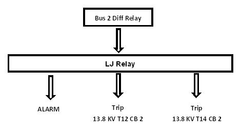
Solution – The LJ relays can serve as a contact multiplier. LJ relays are ideal for this application as the rated contact closing time is 4 ms.
This application is illustrated in Figure 6 where a bus differential relay for Bus 2 actuates an LJ relay that trips the two sectionalizing circuit breakers that are connected to Bus 2 (shown in Figure 4).

Figure 6 – Illustration of LJ application for Contact Multiplication
